isDesign® Work flow
Creating a new Member
Click on Job Properties and fill out appropriate parameters for the job.
![]()
Next click on add New Design in the navigation menu and select a member type.
After the initial install it is recommended to set all of the defaults for all of the member types below before designing members.
If you need to add bearings simply click on the add bearing icon on the member toolbar and slide the bearing across the bottom of the member to desired location.
Then if you need to edit the location further, simply click on the bearing and the bearing properties will appear.


Next step is to add loads.
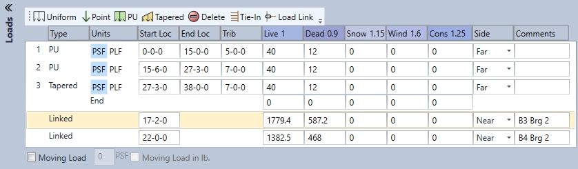
The Uniform load tab distributes a uniform load across the whole member.
The Point load tab includes PLF units and weight units in lbs.
The PU tab (partial uniform) distributes a uniform load across a specified location on the member.
The Tapered load tab distributes a uniform load that is tapered with a specified starting location and ending location with a specified beginning load and ending load.
Delete will delete highlighted loads.
The Tie-in load tab assumes a full length member for your PSF or PLF loading vs. using the tributary method. It also assumes the 5/8 rule for center supports when this load is used.
The Load Link tab allows the user to engineer attached members prior to the current member and allows the user to attach a prior member reaction to the current member and place in the proper location. The use has to define if it is top, near or far loaded
Using the Side drop down menus and defining top, near or far loading is crucial for way Multi-Ply nailing behaves.
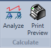
At this point if the user wants to Analyze or see the calc they can click on the "Analyze" button or "Print Preview" button in the member ribbon.
Analyze will give the user several options to view. Click "Run" button to run through any of these 3:
Seek will run through all available products for that member and give the worst case solution out of those products.
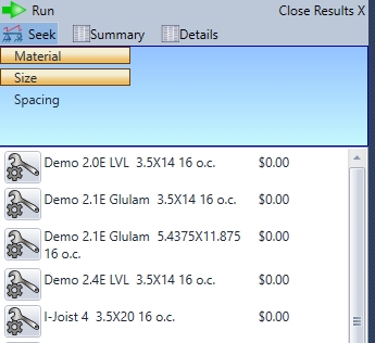
Summary is a calc sheet with more verbose calculation information. Typically intended for the design engineer.
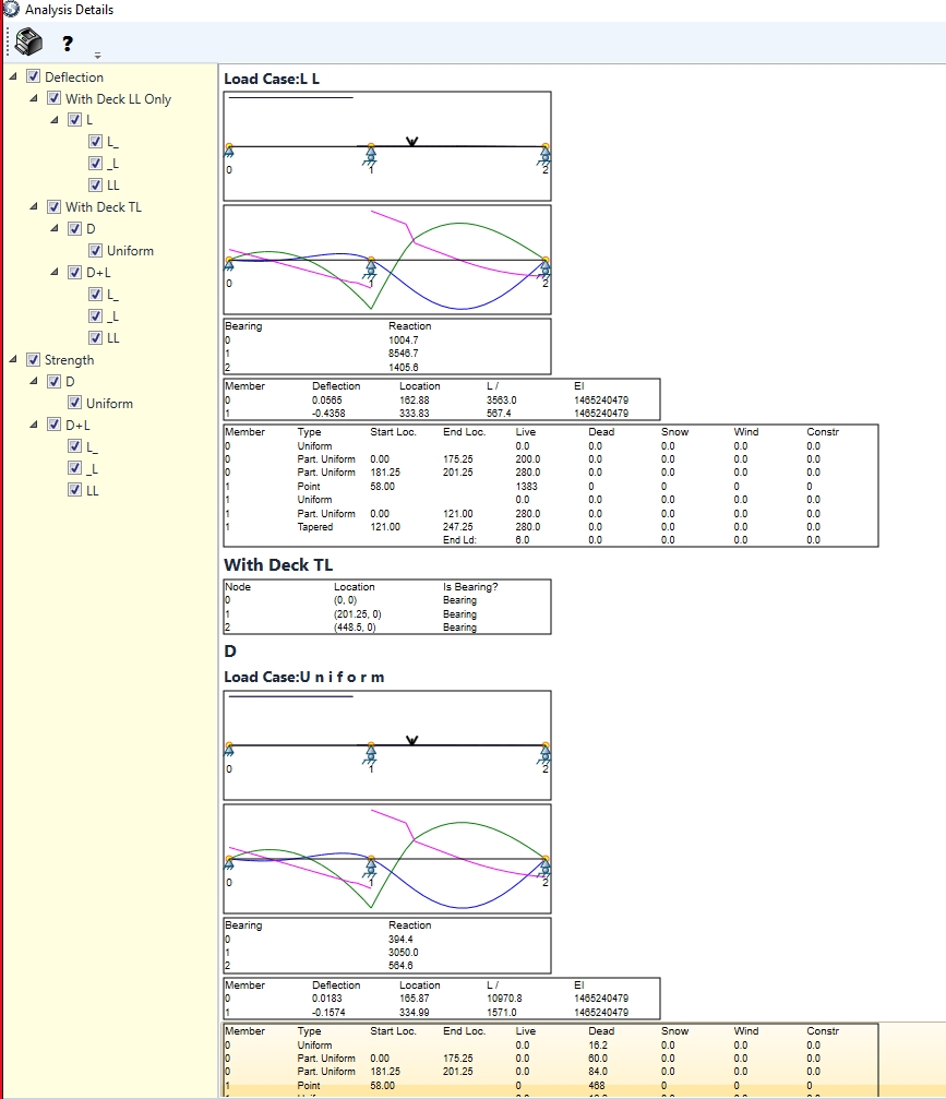
Details is a graphic display including calculation numbers, showing the multiple load case analysis performed on the member.
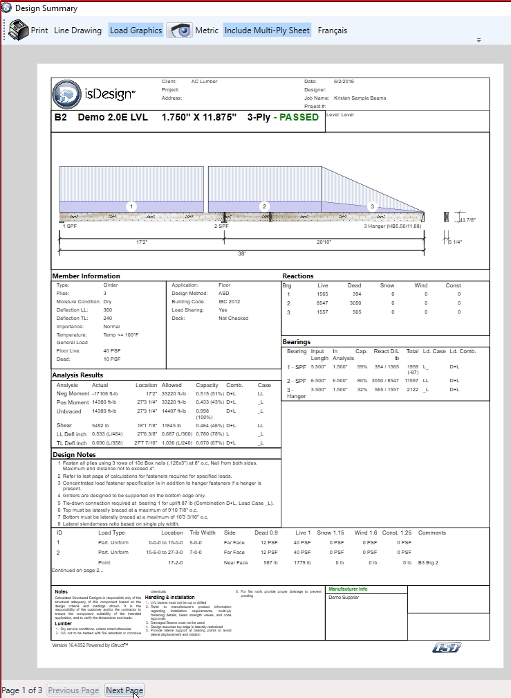
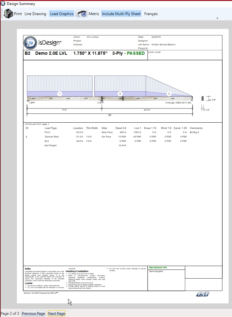
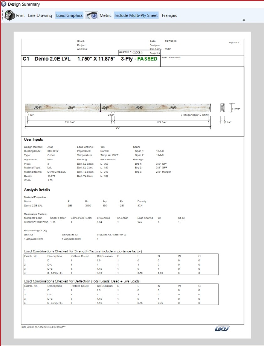
Print Preview displays the member calc sheet. This is the calc sheet that is typically used for submittals. This calc sheet allows users to display a line drawing of the member or a graphic drawing of the member. As well as the following features:
Turning on/off load graphics
A visibility feature that allows turning on/off loads, labels and textures
Metric unit conversion
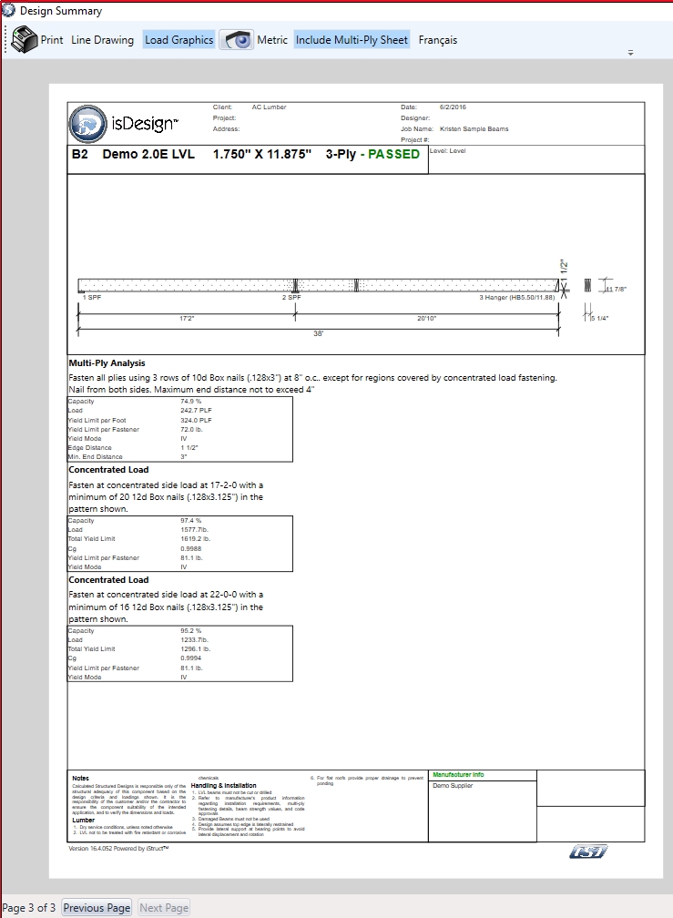
Including Multi-Ply connection sheet (shows nailing , screwing and bolting patterns)
English or French language capabilities