Compression Roof Tool
This New Compression Rood Tool By Calculated Structured Designs is allowing users the capability to create a Compression Roof using the ridge-board tie method vs. a structural beam or both within the same structure.
The Compression Roof Tool will develop loads throughout the roof structure, pass them through to the levels below, allow for over framing, roof plates (to carry valley overframing), columns, skewed columns, and strongbacks for additional bearing.
The user can also define whether or not a member is structural or non-structural.
Members that are not in line at the ridge board will not be considered Compression Roof and will convert to structural.
The Analysis will transfer loads from the Compression Roof and give the user a framing plan with materials for the roof.
The Materials are not engineered!
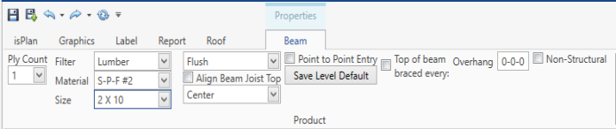
Users switching over from the previous Roof Tool will notice that the input methods are very similar to creating an engineered wood roof. However, this roof system will not be engineered and there are slight input differences between an engineered roof and compression roof system.
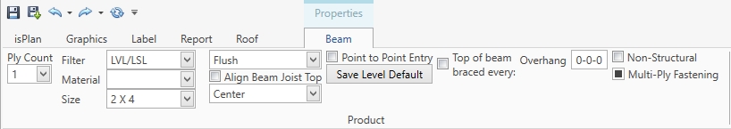
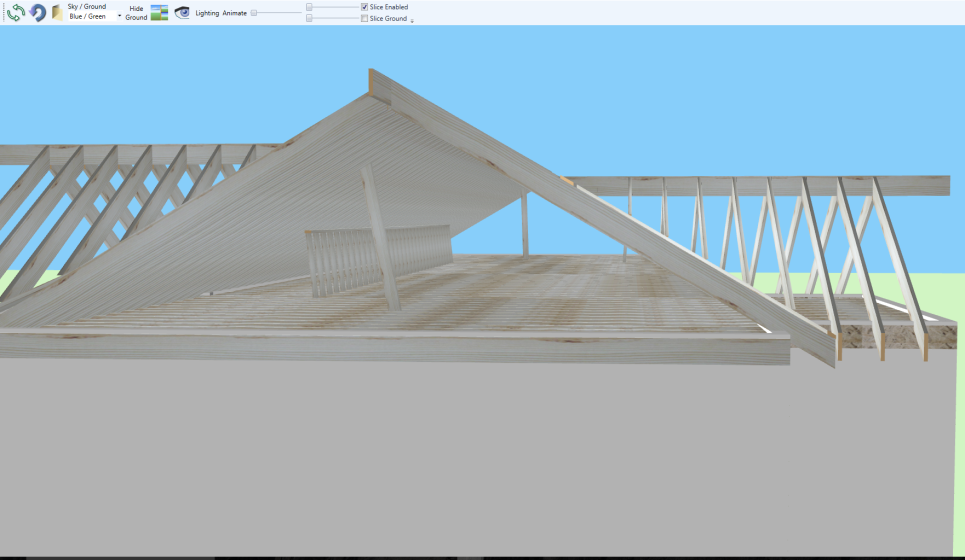
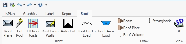
A Roof Beam can be inserted by clicking on a ridge line, plane line, or point-to-point entry. To adjust it to the plane you can right click on the beam and "align to the top of bottom of the roof plane".
Clicking on non-structural can convert a ridge beam to a ridge board. (Non-Structural being ridge-boards used for Compression Roofs typically)
Non-Structural and Structural can be used throughout the layout.
Adding the Roof Plate is typically used for carrying the over framing from a valley, or an application where the user would need a plate on members below to attach to. The Roof Plate is in the flat orientation so the valley joists can attach properly to the rafters below the valley. This function will apply a point load on members that the Rood Plate is attached to if the Non-Structural button is clicked off.
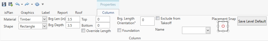
Adding a Roof Column is primarily the same as adding a column for a floor except that now the user can input a Column that is skewed (Slanted) by clicking on an apex of valley and then clicking on a lower bearing that is offset. The Column will recognize the correct heights, even on the skew.
A Strongback (kicker wall) is used for needed support of a roof joist system to a ceiling below (for example see illustration below)
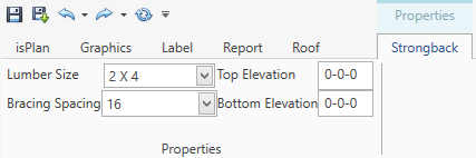
The user simply clicks from point-to-point, then the software will ask where the spacing point starts (start point for studs in the strongback) and the user clicks that point. The software will automatically detect where the bottom of the joist above the top or the joist below are.