Inputting Walls
-When drawing walls it is best to start at the start joist run. *Note: if user does not set a specific start joist run the program will begin drawing walls from the default origin.*
From this point users are able to use arrow keys on keyboard to draw the walls. (example up, down, left, right) Using the arrow keys indicates the direction and distance.
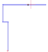
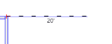
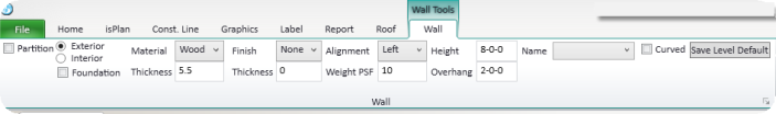
*Users should take notice of the top left corner to see what they have inputted* For example the following picture indicates a direction of up and 20': 
*note: walls are generally inputted in a clockwise direction but this depends on the wall *
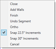
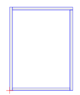
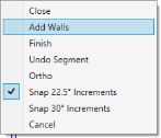
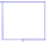
Once you have amount of walls you want you can right click the mouse and click the close option; this closes off the walls to the beginning of the input sequence. The left below picture indicates the right click mouse options and the picture on the right shows the closed wall sequence.
If users are wanting to add up multiple dimensions in the wall command pick the origin and start using your arrow keys and dimensions to add up the walls.
Please see below for two examples:
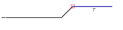
A user can go right 10' right 10' then left 5' the following picture shows the commands just entered: 
Or right 190900 dimension:19'9" right 130900 dimension: 13'9" as seen below and right click add walls to complete the demand

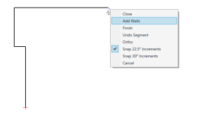
From this point users can then pick a start point to continue adding in walls. When completed right click add walls this is what users should see:
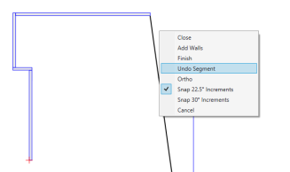
*Note: when users make a mistake they can right click undo segment:
When adding in walls users can hold the CTRL key to lock the angle and then pick an off set point. This allows users to add in walls that are started from a point within another wall segment: see below image as an example.
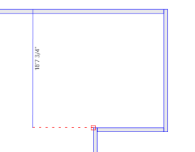
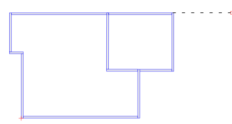
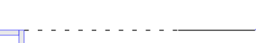
iStruct® allows a users the ability of offsetting the start point. Pressing the "O" key to offset the start point instead of drawing end the offset distance the same as the user would to draw a wall. Below images are examples of offsetting by 20'.

After entering an offset point users are then able to draw a wall. For example below image indicates your offset from the previous wall and has a 10' wall now placed after the offset point

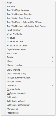
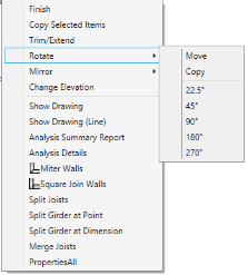
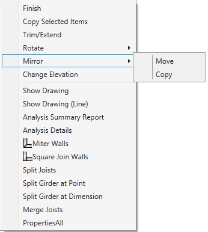
Once walls are added users have several right click options as shown below:
There are a couple ways in which a user is able to enter angles in the iStruct® software
1st input method: Cross Section angles:
Users are able to get a cross section angle by entering vertical and horizontal dimensions together and hitting enter key. iStruct® will create an angled wall between the start and end point from this command. Please see below images as an example
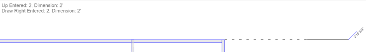


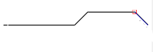
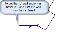
Finishing off this sequence will be a 10' wall on the right of the last angled wall. Users can see the left starting wall in the offset section of the walls section of this document where a 10' wall was placed.

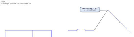
2nd input method: Pressing the "A" key will set the angle (*Note: vertical is 0° and right is 90°*) When using the arrow keys this will rotate each arrow to the right of the angle set. When the angle is set all the arrow keys will work on that angle until you set the angle back to 0° or exit the command. For example setting an angle of 33° from the corner of your last wall segment it will place the angle 33° from that point and continue to draw at a 33° as seen in below pictures.
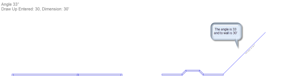
This next picture will show a sequence of walls being inputted at a length of ↓30' → 5' ↓10' ←5' (*Note: the arrows are keyboard arrow indicators ie. ↓down, ←right,↑up,→left*)
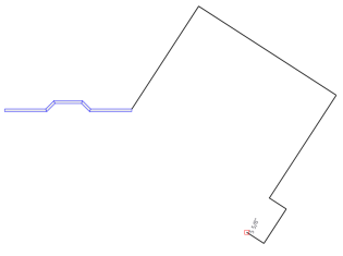
When the last 5' wall has been entered users can reset the angle to 0° by using the "A" key and entering 0°. The next wall inputted will be at an angle of 90° from the corner of that 5' wall. This can be seen in below image: