Drawing Tools
These are the tools that are used to draw the elements of the structure.
To get out of a selection hit the esc key, or right click finish.
Refreshing display [ ] clears any extra items off the drawing.
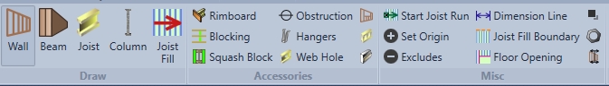
Draw Menu- Inputting Tools
Inputting Wall Menu

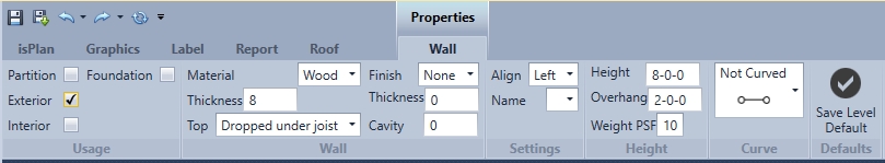
Use this command to draw in exterior, interior, partition, foundation and curved walls. Also within this command wall materials, height and elevations can be changed.
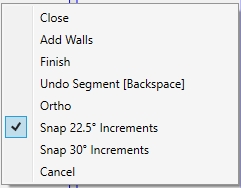
Many execution commands are performed with a right click. For example see below image. If users want to input a single wall and then decide to continue you would use the add walls command. If users are done with the command they can click finish or esc, or users can just click on another input item. Ex: beams, joist, rim.
Exterior is typically the exterior wall of the building. These walls can be load bearing, non-load bearing. This wall material type can be wood, concrete or masonry. Gravity loads will be passed through all walls except for partition walls.
Wall thicknesses reflect actual bearing for members. Example: if you have a 8 inch concrete wall with a joist sitting on top of it that joist will have 8 inches of bearing the top plate is not looked at, at this moment. Coming soon
Interior- Can be load bearing or non-load bearing. Wall material can be wood, concrete or masonry, and will not stop joist from going over it. Loads from above will pass through. Actual width is bearing reflected.
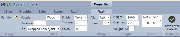
Partition Wall- is non-load bearing wall and loads will not pass through. Members will not see bearing on a partition wall.
Foundation- this feature tells the software that loads passed down have a resolve/an ending. Example: If columns in a level above (other than a ground floor) are passing loads. If you click foundation on that member loads will not be pass through to a level/member below.
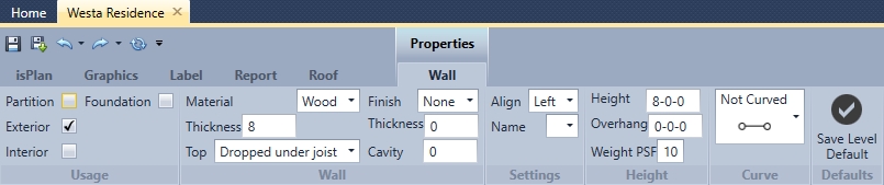
Finish- (brick, siding, stucco) is used for referencing dimensions to the exterior of finish.
Thickness- adds a thickness to the finish.
Top This option is used for creating a flush or a dropped wall
Cavity-This is the distance (space) between the brick and the wall.
Material- wood, concrete, or masonry- is the material of the wall.
Thickness (inches)- thickness of the wall.
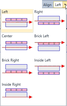
Alignment- (alignment to wall portion) example: left alignment will be on the right of the reference line in a clockwise fashion. Example: using brick will reference to exterior of brick thickness used.
Weight PSF- reflects wall dead load weight in pounds per square foot units. Example: you have a 8 ft wall that is 10 lbs PSF, the wall weighs 80 lbs per foot
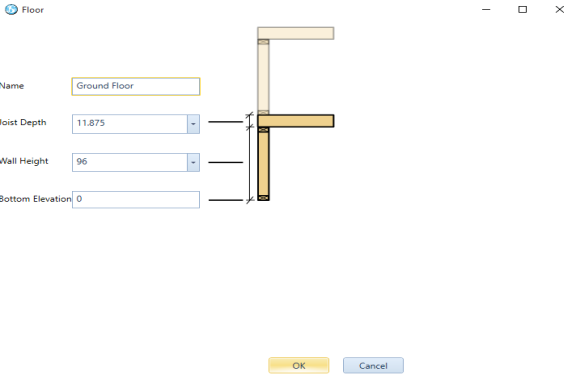
Height-The height is the height of the wall only. In below image it shows height as 96
Overhang- This tells the software that an overhang is to be applied when drawing roofs. Distance from outside edge of wall to end of roof plane defines the overhang.
Name- Drop down shows pre-configured wall style from options/materials list/wall and will automatically transfer properties by selecting the name of the wall
Curved wall-
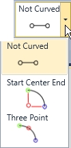
When click on curved wall it will provide 2 input methods. It will provide the option of Start Center End by using the radius as the center point of the curve. Three Point option is using a point along the curve for the description of the curve.
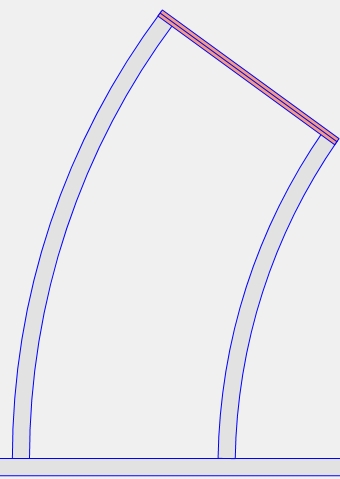
Curved walls use construction points for input users must make sure that °snap is not selected to be able to pick the proper points on the curved wall
Save level default- Saves all the rimboard properties with that specific job in that specific level. Restarting or exiting the program will lose that default.
More on inputting Walls: Inputting Walls
More on Curved Walls: Curved Walls
Wall Editing menu
Selecting multiple or single walls, beams, joists, columns, rim or other framing items create a tab at the top for editing« . Selecting a specific properties tab will allow users to edit a singular or multiple walls, beams joists, columns, rim etc.
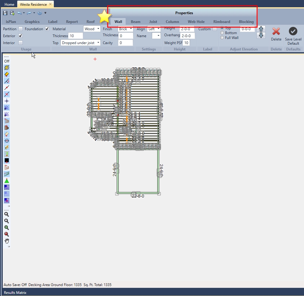
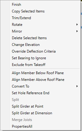
When users select a wall for editing and right click this menu (pictured below) appears. These items are available for use in editing the wall segment or segments.
Wall Right Click:
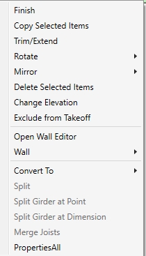
Finish- completes the command.
Copy Selected Items- allows for multiple copy & paste of members selected.
Trim/Extend- trims selected items to a specific member.
Rotate- Rotates selected items
Mirror- Copies or moves original selected items to specified reference.
Delete Selected Items- Deletes items users have selected.
Change Elevation- This is used to check or change elevations (height of members) of any or all items within the framing plan.
Exclude from Takeoff- Excludes items from material list and takeoff.
Open Wall Editor- If a user has isWall they can import a layout wall to the wall editor of isWall to create a Tall Wall design.
Wall- Allows for editing of selected wall segment (see image below)
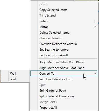
Convert To- allows for a selected member to be converted to a wall or beam
Split- can split a selected wall at a specific desired location
Split Girder at Point- splits a selected girder at a desired location
Split Girder at Dimension- splits a selected girder at a specified dimension location
Merge Joists- merges split joists into one.
PropertiesAll- displays all properties associated with the selected member.
The following images explain the subcategories of the above right click details picture:
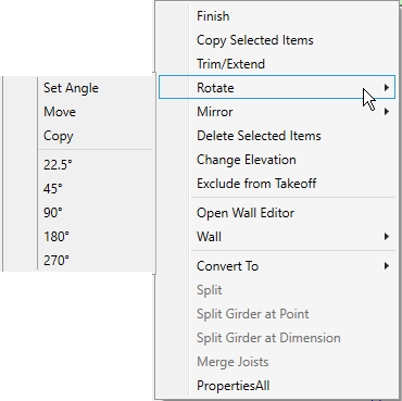
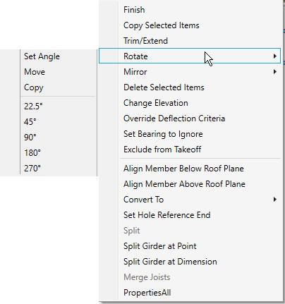
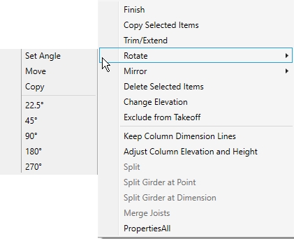
Rotate- A selected wall can be rotated by a set angle, or a predefined angle as seen on the left.
Move- gives the user the capability of picking the rotation point for rotating a wall.
Copy- gives the user the capability of using the user defined rotation point for copying a wall
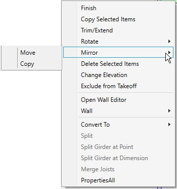
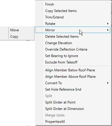
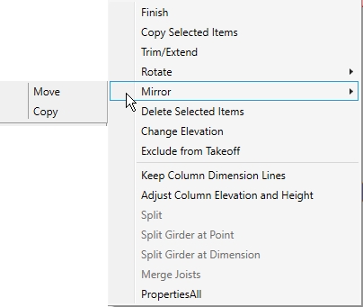
Move- allows users to mirror a item or a group of items or structure to a defined mirror line. This includes mirroring on an angle as well as long as the defined mirror line is on an angle.
Copy- Allows the user to copy an item, group of items or a structure to a user defined mirror line.
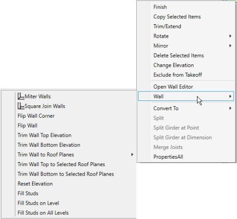
Mitre Walls- by selecting two walls and clicking miter users will create a miter corner
Square Join Walls- by selecting two walls and clicking square users will create a square corner
Flip Wall Corner- changes the framing combination for the corner of a wall
Flip Wall- uses the opposite alignment line of the wall
Trim Wall Top Elevation- users select which wall they would like to trim and the software will automatically recognize what members are above or below it. Then the user selects which member they want to trim top elevation to.
Trim Wall Bottom Elevation- users select which wall they would like to trim and the software will automatically recognize what members are above or below it. Then the user selects which member they want to trim bottom elevation to.
Trim Wall to Roof Planes- allows a user to trim a wall to the roof planes or under roof joist.
Trim Wall Top to Selected Roof Planes- allows the user to trim the top of the walls to the selected roof planes only
Trim Wall Bottom to Selected Roof Planes- allows the user to trim the bottomr of the walls to the selected roof planes only
Reset Elevation- resets the wall elevation to the default defined in edit levels/edit
Fill Studs- fills the selected wall with studs
Fill Studs on Level- fills the current level with studs
Fill Studs on All Levels- fills the entire structure with studs.
Delete selected walls- will delete walls that have been selected.
Elevation can be adjusted- (inches) to lower the top elevation pick up or down arrow and it will change the height in that direction same goes for bottom elevation. Full wall elevation shifts entire wall up or down keeping the height consistent.
Beam

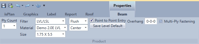
Ply count- sets # of plys that users want the beam to be (1-4). (Joist maximum plies is 2)
Filter- Defines the type of product used for the beam. (lumber, LVL/LSL, I-joist, Glulam, Beam by Others)
Material- Displays a list of product based on the Filter chosen.
Size- Based on material chosen with the Filter and Material drop-down menus the sizes are displayed for that particular item.
Flush/Dropped- Flush beam is flush to floor system. Dropped beam is flush to top of wall.
Align- left, right, centre (justification)
Point to point input- Pick the beginning point and the end point of the beam users want to describe. If turn off point to point it will go along any selected line.
Save level default- Saves all the beam properties with that specific job in that specific level. Restarting or exiting the program will lose that default.
Overhang- This setting indicates the overhang length that will be applied when roof plane is attached to the beam.
Multi-Play Fastening- When multi-ply fastening is checked the appropriate fasteners will be designed for that multi-ply beam. If it is not checked multi-ply fastening will be ignored.
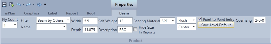
Name- is controlled by the beam by others product name in Options/Material styles/Beam by others
Width- input by the user for the width of the beam by others
Depth- input by the user for the depth of the beam by others
Self Weight- input by the user for the self weight of the beam by others
Description- used for Beam name on layout
Bearing Material- bearing material of the beam by others (SPF, D.Fir, etc.)
Hide Size in Reports- the size is hidden in Layout/Quote/Cutting reports.
Beam By Others are NOT engineered. However, loads are passed through the Beam by Others from above for gravity load development
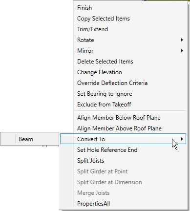
Beam Right Click:
Finish- completes the command.
Copy Selected Items- allows for multiple copy & paste of members selected.
Trim/Extend- trims selected items to a specific member.
Rotate- rotates selected items
Mirror- copies or moves original selected items to specified reference.
Delete Selected Items- deletes items users have selected.
Change Elevation- This is used to check or change elevations (height of members) of any or all items within the framing plan.
Override Deflection Criteria- allows user to override deflection for selected member only
Set Bearing to Ignore- allows user to ignore a bearing that is not needed.
Exclude from Takeoff- Excludes items from material list and takeoff.
Align Member Below Roof Plane- sets the height of a roof member below a selected roof plane.
Align Member Above Roof Plane- Sets the height of a roof member above a selected roof plane
Convert To- allows for a selected member to be converted to a wall or joist
Set Hole Reference End Hole is measured from this dimension which can be left or right side of the member.
Split can split a selected wall at a specific desired location
Split Girder at Point splits a selected girder at a desired location
Split Girder at Dimension splits a selected girder at a specified dimension location
Merge Joists merges split joists into one.
PropertiesAll displays all properties associated with the selected member.
Rotate- A selected beam can be rotated by a set angle, or a predefined angle as seen on the left.
Move- gives the user the capability of picking the rotation point for rotating a beam.
Copy- gives the user the capability of using the user defined rotation point for copying a beam
Mirror
Move- allows users to mirror a item or a group of items or structure to a defined mirror line. This includes mirroring on an angle as well as long as the defined mirror line is on an angle.
Copy- Allows the user to copy an item, group of items or a structure to a user defined mirror line
Convert To- Converts the selected member to a wall or a joist.
Joist

This allows for individual joists to be added to drawing, similar to beam feature. (this command is used for adding 1 joist at a time only, see Joist Fill for adding multiple joist to a layout)
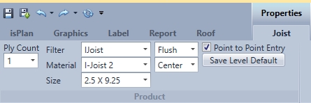
Ply count- pick # of plys that users want the joist to be (1-2)
Filter- Defines the type of product used for the beam. (lumber, LVL/LSL, I-joist, Glulam, Beam by Others)
Material- Displays a list of product based on the Filter chosen.
Size- Based on material chosen with the Filter and Material drop-down menus the sizes are displayed for that particular item.
Flush/Dropped Flush Joist is flush to floor system. Dropped Joist is flush to top of wall.
Align- left, right, centre (justification)
Point to point input- Pick the beginning point and the end point of the beam location users want to describe. If turned off point to point it will go along any selected line.
Save level default- Saves all the beam properties with that specific job in that specific level. Restarting or exiting the program will lose that default.
Identical with beam but joist allows up to 2 ply and joist material flush or drop center along point to point entry- places product in as joist object wet condition will disappear depending on product (for exposed deck)
Joist Right Click:
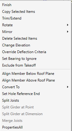
Finish- completes the command.
Copy Selected Items- allows for multiple copy & paste of members selected.
Trim/Extend- trims selected items to a specific member.
Rotate- rotates selected items
Mirror- copies or moves original selected items to specified reference.
Delete Selected Items- deletes items users have selected.
Change Elevation- This is used to check or change elevations (height of members) of any or all items within the framing plan.
Override Deflection Criteria- allows user to override deflection for selected member only
Set Bearing to Ignore- allows user to ignore a bearing that is not needed.
Exclude from Takeoff- Excludes items from material list and takeoff.
Align Member Below Roof Plane- sets the height of a roof member below a selected roof plane.
Align Member Above Roof Plane- Sets the height of a roof member above a selected roof plane
Convert To- allows for a selected member to be converted to a beam
Set Hole Reference End- Hole is measured from this dimension which can be left or right side of the member.
Split Joist- can split a joist at a specific desired location (typically over a wall or a beam where each joist will find bearing)
Split Girder at Point- splits a selected girder at a desired location
Split Girder at Dimension- splits a selected girder at a specified dimension location
Merge Joists- merges split joists into one.
PropertiesAll- displays all properties associated with the selected member.
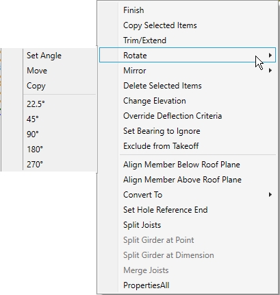
Rotate- A selected wall can be rotated by a set angle, or a predefined angle as seen on the left.
Move- gives the user the capability of picking the rotation point for rotating a joist.
Copy- gives the user the capability of using the user defined rotation point for copying a joist
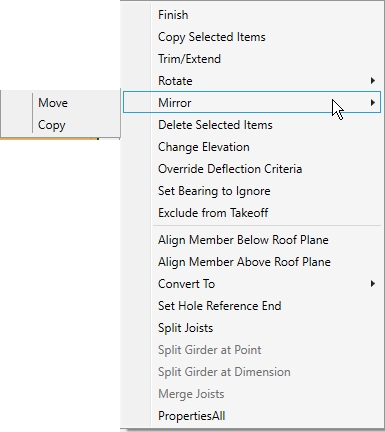
Mirror
Move- allows users to mirror a item or a group of items or structure to a defined mirror line. This includes mirroring on an angle as well as long as the defined mirror line is on an angle.
Copy- Allows the user to copy an item, group of items or a structure to a user defined mirror line
Convert To- Convert member to a beam
A joist cannot be converted to a wall only a beam!!
-Column

Columns are added to beams for support. Axial forces are transferred through all columns that are lining up within a structure including: column by others, designed wood (proprietary wood product columns) and proprietary steel.
Use snap tools to keep centred with beam and walls. This only works with beam items. See tutorial for more information on how to input columns.
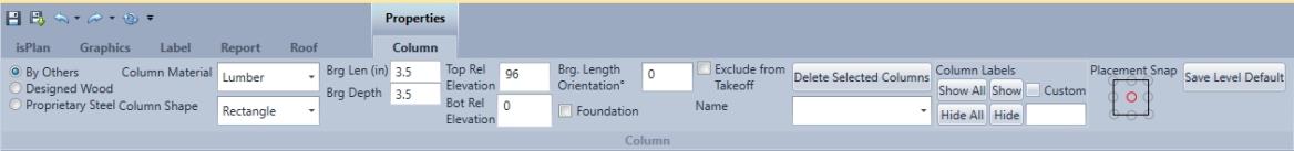
By Others
Column material, column shape (effects 3D only), bearing length, bearing depth, will automatically re-size by beam.
Designed Wood
Product, size, plies, Cap Width and Cap Depth are used when inputting a proprietary column.
![]()
Designed wood (proprietary columns) are engineered for axial forces and can be sized for appropriate loads applied. Gravity load analysis will also be automatically applied to designed wood columns.
Proprietary Steel
Series, bearing length and bearing depth are used when inputting a proprietary steel column.
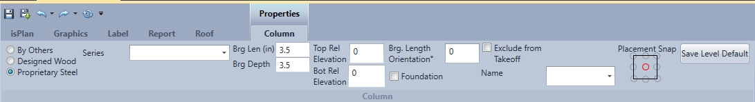
Proprietary Steel- is engineered for axial forces and can be sized for appropriate loads applied. Gravity load analysis will also be automatically applied to proprietary steel columns.
Top Elevation- automatically adjust to the underside of the supporting beam
Bottom Elevation- bottom of column elevation is 0. 0 is the bottom of the current level
Bearing Rotation- X-Y- as numbers change rotates accordingly
Exclude from Takeoff- it will not include the product in material list
Delete Selected Columns - applies to a single column or multiple selected columns and filters only columns selected.
Name- allows to pick pre-existing column styles in options
Placement Snap- when click to place a column, the placement snap shows the reference place to snap the column to.
When placing a column use arrow keys to offset and locate.
Left click will place new column. Use esc key or right click finish to get out of command.
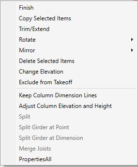
Finish- completes the command.
Copy Selected Items- allows for multiple copy & paste of members selected.
Trim/Extend- trims selected items to a specific member.
Rotate- rotates selected items
Mirror- copies or moves original selected items to specified reference.
Delete Selected Items- deletes items users have selected.
Change Elevation- This is used to check or change elevations (height of members) of any or all items within the framing plan.
Exclude from Takeoff- Excludes items from material list and takeoff.
Keep Column Dimension Lines- allows user to keep the dimension lines that the software generated when inputting multiple columns. As users input the multiple columns, the software dimensions automatically to the columns.
Adjust Column Elevation and Height- the user can adjust the height of the top and/or bottom by selecting the member above or below it is going to trim to.
Split- can split a selected wall at a specific desired location
Split Girder at Point- splits a selected girder at a desired location
Split Girder at Dimension- splits a selected girder at a specified dimension location
Merge Joists- merges split joists into one.
PropertiesAll- displays all properties associated with the selected member.
Rotate- A selected column can be rotated by a set angle, or a predefined angle as seen on the left.
Move- Gives the user the capability of picking the rotation point for rotating a column.
Copy- Gives the user the capability of using the user defined rotation point for copying a column
Mirror
Move- Allows users to mirror a item or a group of items or structure to a defined mirror line. This includes mirroring on an angle as well as long as the defined mirror line is on an angle.
Copy- Allows the user to copy an item, group of items or a structure to a user defined mirror line
Joist Fill

Used to fill in joists on a framing layout and inputs the joist in an array fashion. Two methods are used for inputting: draw run line and exterior boundary/boundary.
Draw Run Line- the user can select a beginning and end point for where they would like the joists to be placed using the inches o.c. spacing. This will create a joist region.
Exterior Boundary/Boundary- the user can select the exterior and interior walls, beams, in a clockwise fashion to describe the boundary that the joists to create the joist region.
Joist fill will stop at all exterior walls, flush beams, rimboard and the Joist Fill Boundary line.
The Outer Boundary Method:
When using the outer boundary method pick a start point and click on exterior walls going in clockwise direction. After users have created the boundary users can left click to define the joist framing area properties to better define the joist directions, start points and references.
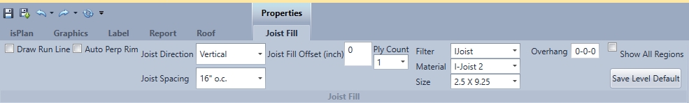
Joist Fill Menu:
Draw Run Line- when selected this will turn on the Draw Run Line method. Leaving this off uses the outer boundary method.
Auto Perp Rim- inserts rim automatically on perpendicular walls within the joist region
Joist Direction- within the drop-down menu users have the option of vertical, horizontal or other direction. This defines the direction reference of the joist.
Joist Spacing- within the drop-down menu users have the option of 8" o.c., 12" o.c., 16" o.c., 19.2" o.c., and 24" o.c.
Joist Fill Offset- offsets first joist from start point by giving distance in inches
Ply count- single or 2 ply are allowed for I-joist or LVL/LSL as a joist member.
Joist product selection - the Filter, Material, and Size are selected from drop-down menus to define the member.
Show All Regions- shows all joist boundary regions.
Save Level Default- Saves all the rimboard properties with that specific job in that specific level. Restarting or exiting the program will lose that default.
Draw Run Line Method:
When using the Draw Run Line method the user selects a Start Joist Run point and then clicks where they would like to start the joist region and drag the line to where they want to end the joist region. The joist are automatically placed using the spacings specified.
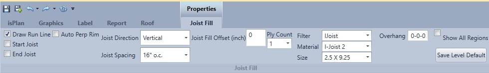
Joist Fill Menu:
Draw Run Line- when selected this will turn on the Draw Run Line method. Leaving this off uses the outer boundary method.
Start Joist and End Joist (first pick point and last pick point) adjust alignment left center or right
Auto Perp Rim- inserts rim automatically on perpendicular walls within the joist region
Joist Direction- within the drop-down menu users have the option of vertical, horizontal or other direction. This defines the direction reference of the joist.
Joist Spacing- within the drop-down menu users have the option of 8" o.c., 12" o.c., 16" o.c., 19.2" o.c., and 24" o.c.
Joist Fill Offset- offsets first joist from start point by giving distance in inches
Ply count- single or 2 ply are allowed for I-joist or LVL/LSL as a joist member.
Joist product selection - the Filter, Material, and Size are selected from drop-down menus to define the member.
Show All Regions- shows all joist boundary regions.
Save Level Default- Saves all the rimboard properties with that specific job in that specific level. Restarting or exiting the program will lose that default.
Joist Region Right Click:
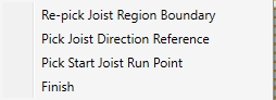
Re-pick Joist Region Boundary- allows for user to reselect the Joist Region Boundary
Pick Joist Direction Reference- allows for user to reselect the direction of the joist
Pick Start Joist Run Point- This is the point where the spacing of the joist region will be pulled from
Finish- Closes the command