Overview
isWall® is is a stand-alone application that allows users to model a wood wall and design it’s various components for gravity and wind loads simultaneously. Users can also generate quotes, member calculation reports and installation drawings from the same model. Various materials are available for design including dimension lumber, LVL, PSL, LSL and Glulam
Design Assumptions:
Calculated Structured Designs (CSD) assumes that the person using this software has a working knowledge of Tall Wall Design. This includes standard construction practices and development for both gravity and out of plane wind loads. isWall® will transfer loads and provide analysis results based on the model created by the user. It is the user’s sole responsibility to determine if the model and results are appropriate and reasonable.
isWall® supports ASD and LSD design methods. Users can choose the method appropriate for their building code.
For ASD (U.S. building codes) isWall® design methodology is based on methods, formulas and wind maps fromASCE7-10.
Many designers are accustomed to using wind speeds published in ASCE7-05. In the 2010 edition wind speeds were increased and adjustment factors were added for load combinations. It is important to verify the appropriate wind speeds with 2010 wind speed maps for use in isWall®.
For LSD (Canadian building codes) isWall® design methodology requires the designer to manually enter the wind pressure that should be applied to the wall. isWall® currently does not support wind speed input. Users need to apply all appropriate adjustment factors to the required wind speed and determine the wind pressure to enter into isWall®.
For all building codes: Currently wind loads are collected from openings and transferred via headers/header plates and sill plates to adjacent king studs and columns as lateral point loads. (these can be seen on the vertical member report)
isWall® currently does NOT design opening headers for out of plane wind loads (bi-axial). Opening headers are only designed for gravity loads. If an opening is wider than it is tall isWall® will warn the user that the header should be reviewed for out of plane wind loads.
isWall® currently does NOT design member connections. Member design reports show the lateral reactions for members. Designers can use these loads to determine appropriate connections such as toe nail, angle clips or hangers. These accessories can be called out in the model using current modeling tools outlined in the following sections.
isWall® analysis currently limits opening positioning such that openings must stack and does not allow for an opening to overlap multiple openings above or below.
Future updates to isWall® will add header wind design as well as connection design.
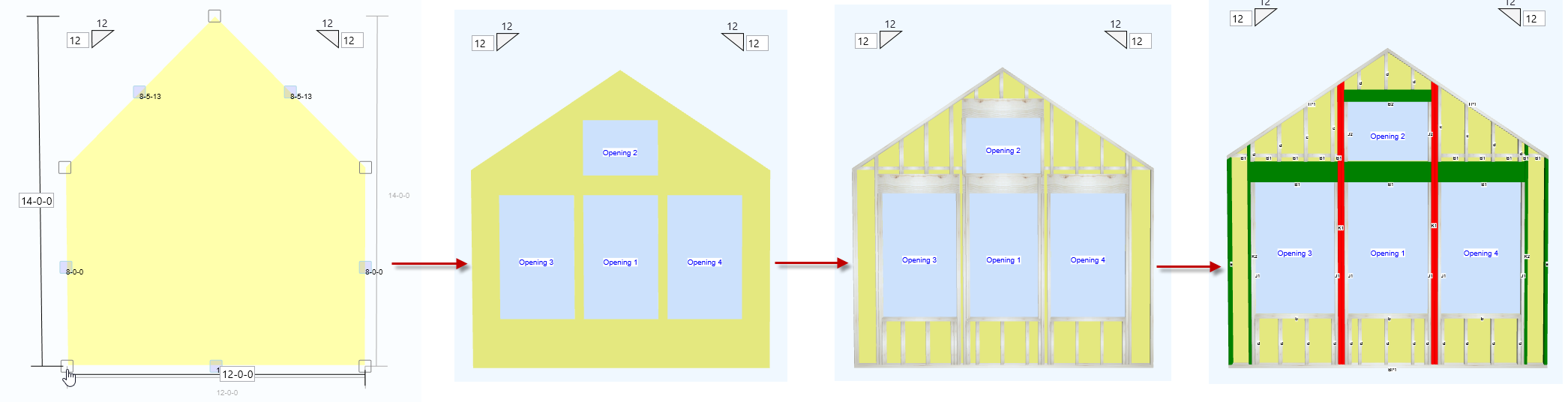
Work flow:
The recommended work flow in isWall® is to create a wall outline or shape that represents the wall. This wall outline or profile is represented on screen as a shape made up of line segments with center and nodes. These nodes and segments are editable. Users can also add nodes to create custom shapes including sloped segments and steps.
Once the wall outline is defined the user should add the openings that are required for the wall. The opening tool allows users to define the shape of the opening including sloping the top or bottom of the opening. Users can also assign specific member properties to the opening that impact how the wall will be framed.
Once the wall profile and openings are created then the wall can be framed using the material properties contained in the wall information window combined with opening material selections. After framing the wall the user can make appropriate edits and changes.
Finally the user should add appropriate gravity loads, wind loads and run analysis on the wall. Next, fix any failures and deal with any warnings that might come up.
After design, the user can create a quote or layout as required.
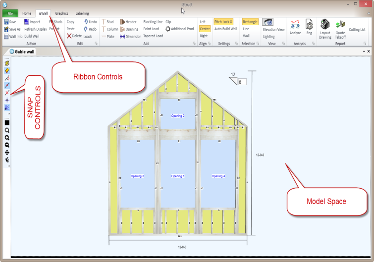
isWall® Interface
Selection Controls
 There are multiple ways to select an object in the isWall® model. Simply clicking on an object will select it. Using the control key will allow multiple objects to be selected by clicking on them while holding the ctrl key at the same time. The main ribbon has a couple of selection controls that help with member selection. “Rectangle” selection allows you to use the mouse to click and drag a rectangle across objects that you want to select. All objects that the rectangle crosses will get selected. “Line” selection allows you to use the mouse to click and drag a line across objects to select them. “Wall” selection will also include the wall outline in the selection group
Zoom tools for 2D and 3D
isWall® contains tools to help manipulate the wall in the model space. There is a toolbar on the left side of the model space with the following tools.
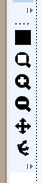
- Zoom Extents: Zooms the view to the extents of the
- wallZoom in: makes the model larger
- Zoom out: makes the model smaller
- Pan: Depress the left mouse button and hold to pan the wall
- Rotate 3D : Depress the left mouse button and hold to rotate the wall
While in the model space holding the control key while spinning the mouse wheel will increase the speed at which the model is zoomed in or out.
While in the model space holding the "D" key while depressing and holding the left mouse button will activate the 3D mode so the model can be rotated in 3D
Visibility Controls
The visibility control (eye button) on the main isWall® ribbon allows users to control visibility for every object in the model.
Starting a New Wall Design
From the iStruct® Home Screen choose “New isWall®” to begin a new wall design.
Wall Information Dialogue
When starting a new wall design the user can enter basic information about the wall including material selections and choose the basic shape of the wall. After closing the dialog it can always be re-opening from the “wall info” button on the main isWall® ribbon.
Gernal Info
The General section of the wall info dialog provides space to input information about the wall. These fields can be mapped into output reports. They are as follows:
- Name: a unique name for the wall and also used as the default for the file name.
- Description: add information about the wall design
- Design Method: indicate the analysis method desired.
- Date Created: This field defaults to the date the file is created.
- Due Date: user can indicate the due date if desired.
- Metric: units if desired
- Project Name: This could be the job name, owner name, etc.
- Client: Optional space for the dealer, builder, owner name.
Job Info
The Job info tab provides space to input additional information about the wall project. Users can set the following options:
- Material Style: This sets the pricing file to use for the job.
- Shipping Address: select shipping info is saved in user options
- Sales Rep: indicate a sales person associated with the job
- Designer: Shows the designer info for the wall file
- Engineer: enter optional engineer name if desired
- Manual* Project Number: field for job number
- Manual* Builders Project: project name if wall is associated with other files
- Manual Shipping Address: Manually enter shipping address for the job
- Show Company Address/logo on reports: checkbox to add this info to reports.
Materials
The Materials section of the wall info dialog allows users to set the default material properties for the wall. These settings are used during the “Build Wall” process. Users can indicate desired materials for different parts of the wall. These settings can then be saved into a material style library for future use. The style library streamlines product selection for future wall designs.
Save as Default: make desired material selections in the dialog then click the “save as default” button to make the selections the “default” materials for each new wall.
Save Style: this button will save the current material settings to the style library using a name you choose. You can save as many different material combinations as you like. Just use a unique naming system to make them easy to remember.
Apply Style: This accesses the style library and allows the user to pick a saved material style saving multiple inputs to change the wall material as design needs change.
Making changes here during the modelling or design phases does not automatically update the wall framing. These settings only apply during the Build Wall or Fill Stud commands. Also, this is the only place to indicate wall thickness, stud spacing and number of top plates.
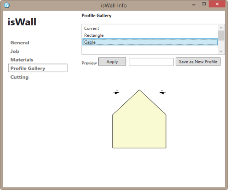
Profile Gallery
The profile gallery allows the user to choose a basic wall shape to start the model with. By default there are two basic shapes, a rectangle and a gable.
Once a user modifies one of the basic shapes in the wall editor they can save the new shape to the profile gallery by simply opening the wall info dialog. Go to the profile gallery tab and the current wall shape (including openings) is shown in the preview area. Enter a profile name in the field provided and click on the “Save as New Profile” button. The new profile will be added to the library for future use. If you do not wish the openings to be saved with the profile you will need to save the profile after creating the wall shape but before adding any openings.
Opening properties are also saved with the profile. This includes header information, header plates, kings, jacks, etc.