isPlan® WorkFlow
User clicks on New Project to start
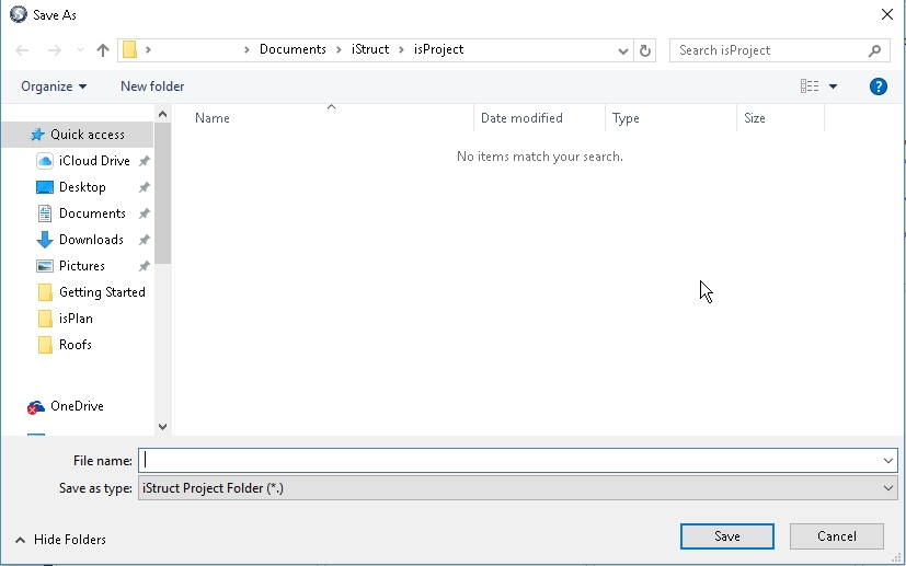
Enter File name to save New Project
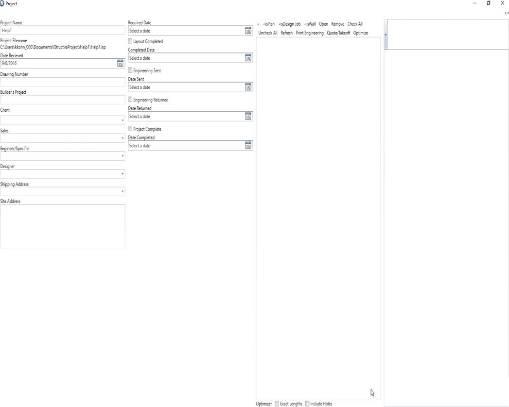
User fills out Customer and Job Information pertaining to the current project. (see below images)
To start an isPlan layout drawing click on +isPlan and the software will start up. Anything developed witin this project will be saved within this Job Tree and Project File.
Clicking on any other of these items will also start that specific Software package or execute that command.
The + sign is for adding additional files such as PDF, DWG, Word Docs, DXF, etc. to the project job tree.
Users take notice that Notes can be added that are pertinent the Project File and by clicking on the + sign the note is then added with a date and time stamp.
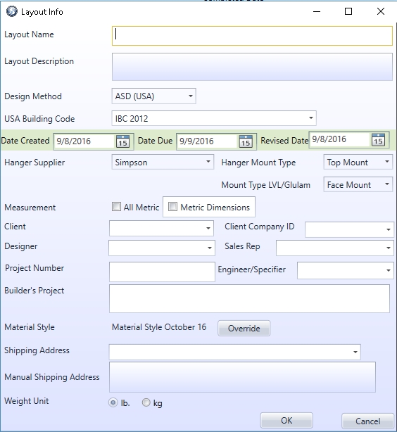
User must create Layout Name and if desired fill out additional fields pertaining to the layout.
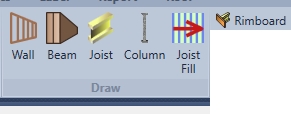
User starts with drawing Walls, then Beams (Flush/Dropped), Columns, Rimboard and Joist Fill.
NOTE: For additional information please see isPlan tutorial
Drawing Beams can be done by using the point to point and click entry method or by using arrow keys (up, down, left, right) method.
Drawing Columns can be done by using the placement snap to define point reference on a member or wall and clicking once to insert that Column. Multiple columns can be input by clicking over the top of an existing column and moving the column in a defined dimension and direction. Using arrow keys (up, down, left, right) method.
Rimboard can be drawn by simply clicking on a specified wall, right clicking and selecting place on all exterior walls and/or point to point entry for specific location of rim.
Joist Fill- After defining the Start Run point or Set Origin point for set spacing (where joist run starts) user can input the Joist Area fill by clicking on Draw Run Line and clicking on exterior walls from one end to the other, defining the longest points in the fill/area that are to be defined with Joists.
Joist is used for adding a single member using the point to point or using arrow keys (up, down, left, right) method.
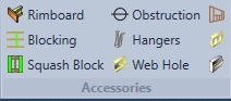
After the basics of the structure have been input the accessories can be added.
Blocking can be added by simply drawing a line from point to point or using draw line on perpendicular areas. (such as parallel ladder framing) The software automatically detects the material/size around where the Blocking will be inserted. The blocking that’s inserted will then be duplicated to the materials around it.
Squash Block can be added by selecting a wall/beam then picking the first start point of where the user would like the Squash Blocks to start and then picking an end point of where they would like to end Squash Blocks.
Obstructions are input by clicking on the layout. (joists will not go through the obstruction)
Hangers can be edited by clicking on hangers then selecting the hanger for editing and changing the details of that hanger. (software selects alike hangers and does not mix different types of hangers together within one selection.) Example: don't select girder hangers and joist hangers within the same selection box.
Webholes can be added in joists by drawing a line from point to point or just through a joist section. Define the Webhole details.
Wall Opening is used to insert a flush or dropped beam with opening parameters attached. (doorway or window with bearing width, header sizes, materials, heights, etc.) Click wall opening, pick the desired wall, pick the reference point, define the direction, define the length of the opening and click enter. Define the Wall Opening details.
Pony/Knee Wall can be inserted by clicking on a wall or using point to point input method. Then defining Pony/Knee Wall details.
Ledger can be inserted by clicking on a wall or using point to point input method. Then defining Ledger details.
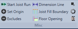
Start Joist Run- is used to define the start spacing point of the Joist Fill being used.
This command is permanent until the user changes it. If you right click and use the Start Joist Run command from the right click menu it only applies to the Joist fill users are currently inputting and is not permanent. So if a user has to re-input that area they must re-define the Start Joist Run using the right click method.
Set Origin- is used to set the 0-x/y starting point for a users layout. If users do not use a Start Joist Run Point the software will default to Set Origin for spacing. This is extremely helpful when lining up multiple PDF files over an existing layout and copying levels to ensure accuracy.
Excludes- will give the user a menu showing which material or members have been excluded from the takeoff. If members have been excluding the use can add them back in by clicking exclude and turing off the members that have been excluded.
Dimension lines -this icon is used to insert dimension lines automatically which will insert all dimensions on a layout or manually draw chain or draw chain lines. This is done by selecting points to draw the dimension to, and on draw chain the user must define the orientation of the dimension. (The orientation is typically that parallel line that the user wants the dimension to use as reference.) Example: The wall that is being dimensioned can be used as orientation.
Joist Fill Boundary- is used to create a cut off line to prevent Joist Fill or single i-Joist from going through a specific area. Example: User may not want joist in same directions as interior wall so they may use Joist Fill Boundary line to prevent Joist from going in the same direction as that wall
Floor Opening- is used to prevent tributary loading within an open area with no framing members in it. Example: a stariwell opening would use floor opening to prevent tributary load from going through it.
Decking - This command is used to input decking in an area type fashion clicking point to point to point to create a decking boundary. Or by right clicking and automatically generating decking (note: automaticaly adding decking will only apply decking to joist covered areas) and/or clearing decking from the layout.
Additional products- is used to add products that are not specified within the layout or just products the user would like to add to the materials list for TakeOff and Pricing. These additional product can be custom, wood products, beam by others, columns, hangers
Split- this command is used to split many items such as walls, rim and framing members. Simply click on split, and then "Pick item" to split then "Pick a reference point" (such as the beginning of a wall) then hit "Arrow key end dimension, or enter for no offset" and then hit enter to execute.
Note: User can also click on other members for reference or click on other points for reference to split.

Const. Line Finite- this feature can be used for many things. The input method is from point to point and is used for referencing building geometry, bearing locations, member locations, column points, plane cutting lines, or just a reference from a ghosted level above.
Const. Line Infinite- is used for the same as const. line finite but is input from point to point and creates an infinite line accross the screen for reference.
Const. Line Infinite Snap- if this icon is clicked the user can click on a wall or member and the infinite construction line is attached to that object.
Construction Point- This also can be used for many things. The input method is either clicking on an existing point or member or using coordinates to input this point for reference. Examples of what a construction point can be used for are a radius point for a curved wall, a point for column input, or just a user defined x-y coordinate that needs a reference point.