The User Interface
IsPlan® is divided into a number of major tabs that feature tools related to that section
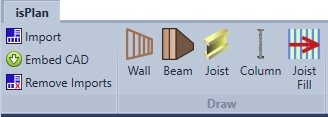
The Primary tab is called isPlan®. This features all the major drawing tools and is divided into sub sections.
Draw which includes Import, Embed CAD, Remove Imports, Wall, Beam, Joist, Column and Joist Fill.
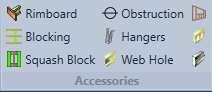
Accessories includes Rimboard, Blocking, Squash Block, Obstructions, Hangers, Web Hole, Wall Opening, Pony Wall and Ledgers.
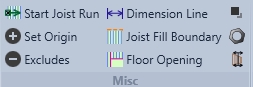
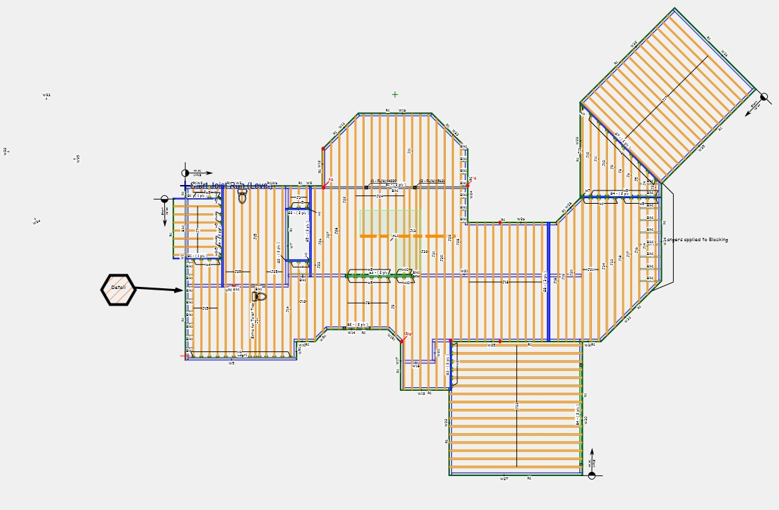
Misc includes Start Joist Run, Set Origin, Excludes, Dimension Line, Joist Fill Boundary, Floor Opening, Decking Additional Products and Split Wall.
Construction Includes Const. Line Finite, Const. Line Inf., Const. Line Inf Line Snap, Construction Point.

Loads- Point Load, Line Load, Area Loads

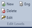
Edit Levels- includes New, Delete Edit, Eng.
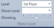
View Level- Level, Ghost Level and Ghosting
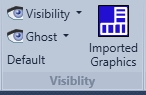
Visibility which includes Visibility, Ghost, Default and imported graphics
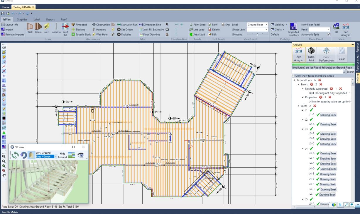
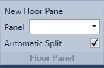
Used for creating floor panels out of a floor system
Used for viewing in 3D and running the analysis of the structure

Snap Toolbar long the left side of the screen are snap tools broken into sections of snap type and the objects to snap to

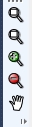
Zoom Toolbar below the snap toolbar is the manual zoom command
Used for the layout drawing space and display of the framing plans
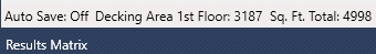
Displays Auto Save on/off- and level total sq. ft. if decking area. Also allows on/off Results Matrix Engineering information
Graphics ribbon is used for adding and editing graphics, text, detail files, notes
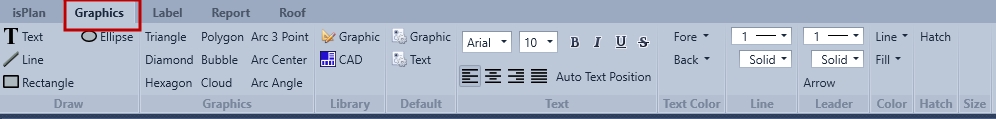
Draw has all the basic geometric shapes needed and includes the text box as well
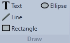
Graphics has additional geometric shapes to add to a drawing for use as call-outs and various line drawing tools.
Library features custom shapes (user created Graphics or notes) that can be saved and added to the Graphic folder for future insertion on a drawing. Imported CAD files can be saved to the CAD libraries folder in the same manner for future use. Once saved a users Custom Graphics and CAD files are stored in these folders.

Default saves the default text size and colours by clicking on the associated icon.

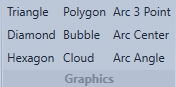
Text is properties for editing text
Text Color is the default for foreground and background colour

Line is the line thickness and pattern default

Leader is for leader thickness and pattern

Color controls the Line, Fill and Hatch colours

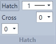
Hatch contains the Hatched Fill, Hatched line thickness, Cross Hatched fill, Hatch Spacing, and Hatch Fill Angle defaults
Label ribbon is used for layout label visibility, editing of dimension text and labels and on/off engineering labels
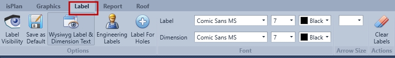
Options Tab:
Label Visibility shows all the label and allows users to turn on or off specific labels

Save as Default saves the current Font tab defaults for Label and Dimension font parameters for your layouts.

Wysiwyg Label and Dimension Text. When the user zooms with the drawing the dimensions and labels adjust in size with the drawing. (Also known as: What you see is what you get)

Engineering Label adds a letter to every different design to match the calc reports when printed. (eg. J1-a)

Label for Holes tells the software to give the hole a unique label

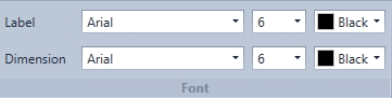
Font allows user to set the Font colour and size of the Labels and Dimensions.
Arrow size is the size of the arrows at the end of the Dimension Lines.

Actions user can clear the labels resetting any numbering.

Report ribbon is used for access of the Layout Drawing, Quote Takeoff, Estimating Data, MBA Export, and Optimization of final layout drawing
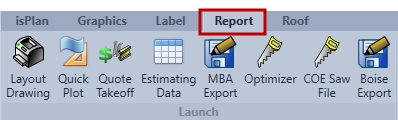
Layout Drawing will run the Analyzes if it hasn't been run and opens the Layout Drawing Report.

Quick Plot will open Layout Drawing without Analyzes.

Quote Takeoff generates a Quote Report or Take off Report.

MBA Export will create a EML file that can be imported into and MBA program.

Optimizer opens isOptimize® (paid add-on) and allows the use to create a cut list from the current layout.

COE Saw File creates an export for the COE saw

Boise Export creates an export file to be imported by the Boise quoting system

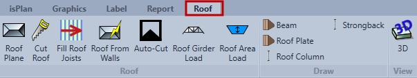
Roof:
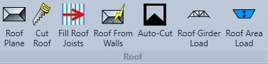
Roof Plan used to add planes to walls and beams

Cut Roof used to manually cut the roof

Fill Joist adds roof joists to selected roof planes

Roof From Walls automatically adds roof planes to walls and solves the roof

Auto-Cut automatically solves manually places roof planes

Roof Girder load used to place girders truss to generate loads

Roof Area Load used to indicate direction of truss and loads

Draw:
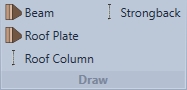
Beam to place beams in the roof

Roof Plate used o add roof plates at valley lines

Roof Column allows users to draw angled lines

Strongbacks is used to add Strongbacks to help support roof members.

View:

3D opens the 3D window